 Inside the Symphony No.1 Amplifier
Here's a picture of the Mosfet modules before
they are fastened to the heatsinks.
The Mosfets have been selected and precision
matched, each individual modules has
the closest match out of hundreds of Mosfets!!
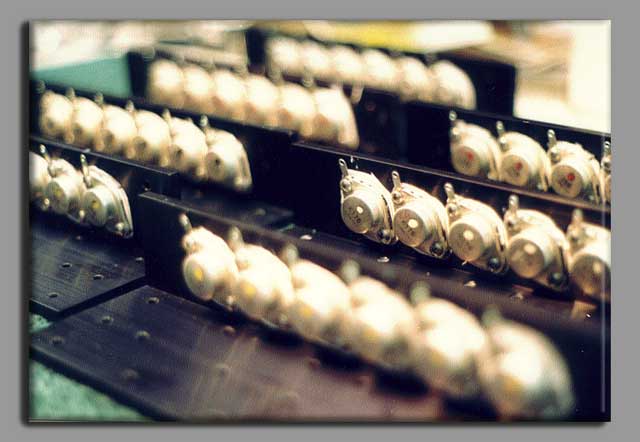
Now you see the module before the Main Amp
PCB is attached and wired in. You can
see the 10ga. wire that is soldered to the
Mosfets. This sends the rail voltage in and
takes the signal back out, with ample current
capacity to spare. I do not use push on
type plugs or connectors anywhere in this
amplifier - all connections use high quality
silver bearing solder - this assures solid,
low resistance connection, and the longest
operational life without breakdown.
.jpg)
Also, note the high quality hardware that
is employed. It is all 100% Stainless Steel
machine screws and nuts. In this image the
standoffs are plated brass. There is nothing
to rust. Note how the Mosfet's module is
fastened to the heatsink! Multiple precision,
CNC machined holes are made in the heatsink,
and in the brackets the holes are tapped.
This provides a very tight fit between the
brackets and the heatsinks to maximize the
efficiency of heat transfer.
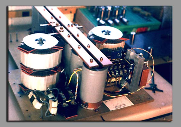 This is the power supply under construction.
You can see the heavy 5/16" aluminum alloy
chassis. Mounted on that chassis are the soft
start relays (to cushion the turn on current),
the control circuit for them, as well as the
power resistors that actually do the work
during the soft start. One can't use a regular
switch to control a power supply of this
size - regular switches would "die young" handling
this load. So, I use relays that have multiple
high-current contacts, and then I use them all
in parallel to minimize the contact resistance!
Each of the contacts is 1/4" in diameter -
compare that to the contact size of even
a 20 amp rocker switch!! Down the center are the
filter capacitors. This bank of caps has
a total capacitance of over 500,000 ufd.!! This
is half a FARAD! In order to transfer the
current and keep the voltage drop low the bank
of capacitors is tied together with solid
copper buss bars that are 1" wide and 1/4" thick.
Then behind that are 4 stacked toroidal
power transformers for a total of over 2.5kVA of
available power.
There's more to come... the rest of the story is being prepared...
When it is all done, this is what it looks
like with the top open!!
